Showing posts with label Electronics. Show all posts

Saturday, August 9, 2014

Sending data over IR with a PIC: the DAC method

Alright, so I had what I thought was a relatively mundane problem: I wanted to send data over IR with a PIC I'm using (specifically, a PIC12LF1572). Should be simple, right? Turns out it's actually a bit of a pain to do in an efficient way, and hopefully it's common enough that my write-up here will be useful to someone trying to do something similar. I certainly looked pretty hard for a solution to this online and didn't come up with anything useful.

This write-up will assume some basic familiarity with microcontrollers (PICs especially) and so I'm not going to spend any time going over the basics like PWM/interrupts/etc.

I'm also not going to go into detail about what my overall project here is right now, instead I'll just focus on this specific solution because I believe it's deserving of it's own post. For now we'll just say I'm working on a generic IR transceiver.

So, why's this an interesting problem? Well, generally when sending data over IR you really want to avoid having all the environmental garbage clutter up your signal (sunlight, a variety of household lights, etc all give off a ton of IR). This is accomplished by filtering out any frequencies that aren't specifically what your receiver accepts, i.e. with a band-pass filter. Because your IR signal has to be sent at this frequency, you actually need to modulate your data with it. For example, if your original data signal looks something like this:

Original data
Then in order to be read by the photodetector your modulated output needs to look something like the blue plotted here:

Original data with modulated signal
So, how do we generate the modulated signal? The most obvious answer would be using an AND logic gate, like so:

Combined signals with AND gate
This is actually a perfectly fine solution in many cases, but there are a couple of major drawbacks which meant that there was no way I could use it in my design. The AND gate adds a whole extra unnecessary component, which drives up the cost of your project (not a big deal if you're just making one, but I'm making 50-100 of these). The other problem is that it requires the use of an additional microcontroller pin (or external PWM source), and considering that I was already making use of all of the output pins on my 8-pin PIC, there simply wasn't an extra pin I could use.

What's the alternative solution? Use the DAC to modulate the data. Seriously. I'll walk you through the process I used to figure this out, and provide the code I used in case you'd like to implement it yourself.

I wanted a decent amount of range with my transmitter, so instead of driving my IR LED at 25mA (the max an I/O pin can safely handle), I decided to drive it with a simple BJT (2n3904). Obviously I wanted the drive signal to be the TX pin of the PIC, so I threw together a quick schematic:


You can see the IR LED hooked up to the BJT's collector, and the base is driven with the PIC's primary TX pin (pin 7), with a series resistor to limit current.

I knew that the photodetector I'm using has a band-pass filter that harshly attenuates signals outside of 38KHz, which means that I didn't have an option other than to modulate my data at 38KHz. As seems to be a common trend with my microcontroller projects, I simply decided "Oh, I'll do something clever in software later." With that, I went ahead and placed an order for a few prototype boards without looking all that closely at the PIC's datasheet.

With the boards on the way, I started cracking on the firmware. To begin with I had some vague notion that I'd write data out using the USART while simultaneously toggling the TX pin between input/output at 38KHz. Well, my boards came in and quickly after soldering one together and checking the data on a scope, I discovered that my original plan wasn't going to work. The USART was writing data out just fine, but unfortunately it just wasn't being modulated at all. The module just overwrites the pin state to output if you set the TRISA register declaring it an input.

Following a couple of days of painful troubleshooting, trying alternative methods, and just generally not getting anything to work, I noticed this unassuming chart right here:

(Taken straight from the datasheet)
Basically, functions higher on the list are able to dominate the state of the associated pin. Notice how pin RA0 (the main TX pin) has 3 functions with a higher priority than the TX function? Well, ICSPDAT is just used for programming so it's not helpful in this case. However, CWG1B (an output of the complimentary waveform generator) and the DAC (DAC1OUT) are both listed as higher priority. That means that if the CWG or the DAC to outputs to the pin while TX is writing to the output buffer, the TX is going to get overridden.

Okay, so that's one piece of the problem, the other one is how to convince the CWG or the DAC to take control of the pin at exactly 38KHz. The CWG is basically able to PWM, so you'd think it'd be the best choice in this case - it turns out that wasn't super helpful because I didn't actually want to drive the pin high then low, I just wanted to change its state between driven and undriven by a specific peripheral. Accordingly it didn't really matter whether I used the CWG or the DAC, so naturally I went with the DAC for extra hilarity (seriously, how can you resist being able to write obtuse comments like "// Enable DAC to send data over serial"?)

I used Timer1 to hit overflow at about 38KHz*2 = 76KHz, triggering an interrupt which toggles the output state of the DAC (which defaults to writing 0V). When the DAC's output is on, it drives the TX pin at 0V, and when the output is disabled the TX is allowed to regain control of the pin state. I also made sure to use a slow baud rate (4545) in order to allow enough 38KHz pulses to sufficiently modulate the signal.

Without further ado, the code:

void Setup(void)
{
    OSCCON = 0b01111010; //16MHz internal clock

    TRISAbits.TRISA0 = 0; // Set RA0 as output
}
void Send_Packet(uint8_t data)
{
    DACCON0bits.DACEN = 1; // Enable DAC to send data over serial
    Modulate_Serial();

    SPBRGL = 54; // Baud rate is 4545
    TXSTAbits.SYNC = 0;  // Asynchronous mode
    RCSTAbits.SPEN = 1; // Enable EUSART
    BAUDCONbits.SCKP = 1; // Inverted mode (idle low)
    TXSTAbits.TXEN = 1; // Enable transmitter

    TXREG = data;
    while(!TXSTAbits.TRMT); // Wait for USART to send all data
    Disable_Modulation();
    TRISAbits.TRISA0 = 0; // Allow RA0 to drive low
    DACCON0bits.DACEN = 0;
}

void Modulate_Serial(void){
 INTCONbits.GIE = 1; // Enable interrupts
 INTCONbits.PEIE = 1; // Enable peripheral interrupts
 PIE1bits.TMR1IE = 1; // Enable Timer1 overflow interrupt

 T1CONbits.nT1SYNC = 1; // Don't synchronize external clock input
 T1CONbits.TMR1ON = 1; // Turn on timer
 TMR1 = 65484; // Initialize TMR1 value for desired frequency
}

void Disable_Modulation(void){
    INTCONbits.GIE = 0;
    T1CONbits.TMR1ON = 0;
}


// Interrupts

void interrupt High_Priority_Interrupt(){
    if(PIR1bits.TMR1IF == 1) // TMR1 register overflowed
   {
    DACCON0bits.DACEN ^= 1; // Use DAC to generate 38KHz carrier wave
       TMR1 += 65484;
       PIR1bits.TMR1IF = 0; // Clear the interupt flag
    }
}

That's pretty much it! All you'd need to do to use this (in MPLAB X with XC8 as your compiler) is add a header file with prototypes for those functions.

He's the final scope shot showing off the modulated waveform, thanks to the DAC:


Yay! Everything works the way it's supposed to.

Over all it was an exciting few days coming up with this somewhat disgusting (but mostly hilarious) hack, and I figured it was actually worth posting about since someone might find it useful. Let me know if you have any questions!

Sunday, March 2, 2014

Audible Altimeter part 1

I was looking for a new electronics project to work on, and found some inspiration in the skydiving world. While you're in freefall, it's absolutely critical to know what altitude you're at, so you can know when to safely pull your parachute. Skydivers wear something along the lines of this so they can keep track of altitude, but another useful indicator is what's called an "audible altimeter", an electronic device that's placed in your helmet and sends out a series of warning beeps at pre-programmed altitudes. I was looking into purchasing an audible altimeter for myself, and found that they're all super expensive (over $200), which seemed pretty ridiculous to me considering how simple they are. I decided it would be a fun project to try and make my own since I thought I could produce one for cheaper, and learn a lot in the process.

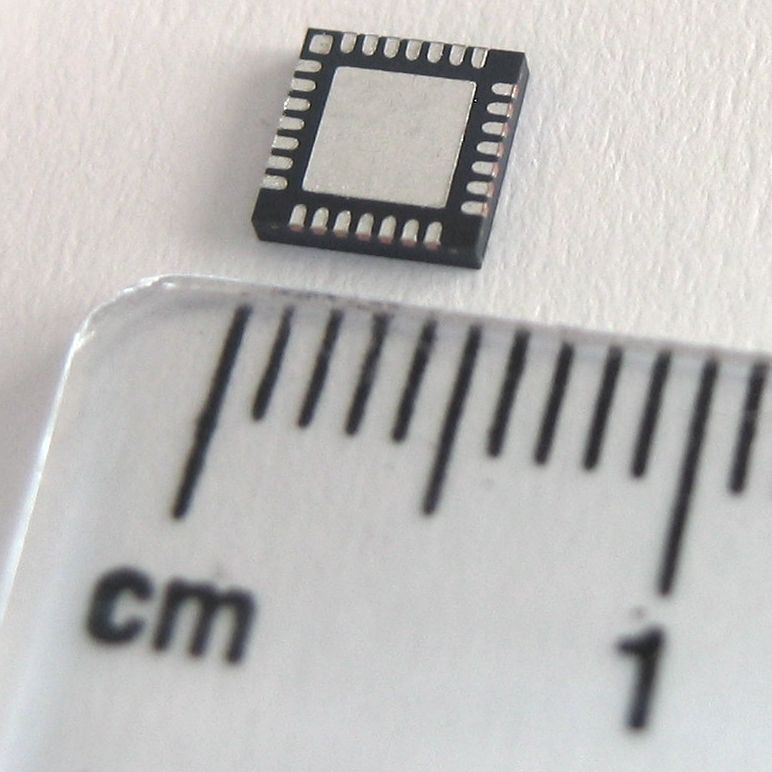
It's definitely an interesting project because everything has to be made as small and low-power as possible, in order to have it be completely portable and so that you don't have to constantly worry about the battery dying. I decided to go with a rechargeable lithium polymer battery (specifically this one) since they have great energy density and charge rates. I found a fantastic chip which is built to charge a single cell LiPo at up to half an amp from a 5V source, which is great for USB charging. I'd also gotten some experience soldering QFN (leadless) surface mount parts over the summer, and I thought it'd be neat to design a board with these to make it as small as possible.

I wanted to branch out in microcontroller selection and pick a new architecture that I could learn about. I ended up going with an STM32F050 because it's quite powerful for how much it costs, and it's a good match for the features I need.

Other than that, I picked:
  • a fast barometer (many of them could only be read as fast as once a second, but this one gives up to 200 readings per second) so that I can get an accurate reading of pressure to calculate altitude from. 
  • a loud 4KHz buzzer so that it would be easy to hear
  • an FTDI USB to UART bridge so that I could program it over USB
  • a 3.3V buck converter, because the LiPo battery outputs anywhere from around 3.6 to 4.2 volts, and everything runs on 3.3V. The buck converter isn't completely necessary because it could be replaced with a linear regulator, but I figured it was worth it to pay a few cents more for something like 20% longer battery life due to the extra efficiency.
  • a bunch of 0603 (metric 1608) passive resistors, capacitors, and LEDs, as well as a few miscellaneous parts like buttons, an inductor, etc.
I started out with a quick block diagram of how I wanted to hook everything up:


I forgot to label Vdd from the STM and the BMP180, but they're going to the 3.3V buck output, not the battery voltage.

I basically sat down for a day or two and CADed all of the part packages using Eagle, and put together a schematic that pretty closely follows the block diagram above, plus a bunch of passives, buttons, and a couple other things.


Unfortunately I was in one of those ultra-focused "make this project without thinking about anything else" states while putting this together, so I forgot to take screenshots showing the process.

One interesting challenge was that I wanted the whole board to be completely powered off while not in use, turn on when a button is pressed, and then be able to turn off when the same button is pressed again. Since I'm only using on/off tactile buttons, I had to get a little creative in order to build this behavior. Basically the buck converter's enable pin (EN) is hooked up to a microcontroller output, so the microcontroller can drive it low to turn off power to everything (including the micro itself). The power button is also hooked up to EN, so that when the board is off and you press the power button, the buck converter turns on, turning on power to the whole board. The micro then has to immediately hold EN high in order for the buck to stay on when you release the button. So far so good, right? The one problem is that the micro has to have a way of knowing when you hit the power button a second time, so that it knows when to turn off the buck and power down. I ended up coming up with a resistor divider pulls a pin on the micro low whenever the micro is driving EN, and pulls the pin high when the button is driving EN, allowing the micro to read the state of that pin to decide if it should power off.

With the schematic out of the way, it was time to lay out/route the board! I wanted all the parts to be on one side so that I could put a battery flush on the other. Here's what I was looking at after placing components:


You can't tell from the picture, but the battery connector (bottom right) is actually on the underside of the board to make it easy to plug the battery into. The yellow lines are "airwires", or connections that haven't yet been physically made. The whole board comes in pretty small at just under 2" by 1", which I'm pretty happy with.

Routing time! This is one of my favorite parts of making boards, it always creates some interesting challenges, especially with smaller boards. Once again, I was in in-the-zone-mode, so I forgot to take pictures of the process.


Looking back I'm a little unhappy with what I consider slightly sloppy routing, all those vias (connections from one side to the other) in the center look pretty messy. Oh well, for revision 1, as long as it works right?

I decided to go with Seeed Studio to get the board fabricated, for smaller boards like this they have an awesome deal of 10 boards for $10, not counting shipping. After placing the order, it was time for the few weeks of eager anticipation that I've come to know over the last year or two since I started making boards.

Of course, it's always worth it when you get a package in the mail and suddenly it feels like Christmas. Here's the top and bottom, with a quarter for scale:


Sorry for the picture quality, maybe one of these days I'll stop spending all my money on skydiving/engineering projects and actually buy a camera instead of using my phone.

Of course as soon as I got these I put everything else aside and rushed to populate one of these with parts, so here's a picture taken a few hours later with everything soldered on:


From there I moved on to trying to turn on the board, and immediately starting having a few problems with the buck converter that it took me a while to get to the bottom of. After decreasing the bypass capacitance on the VCC line I was able to get it to boot up, which allowed me to start programming the microcontroller. Time to learn how the STM32F050 works! Fortunately there's a lot of example code and guides around which make it pretty easy to get things going. I won't go into to much detail about how the code works, I don't think it's useful to paste a bunch of lines of initialization/etc here, so instead I'll describe what I generally did. I started out writing a basic program which holds the buck's EN pin high, turns on the yellow LED, and turns on the blue LED whenever the "ZERO" button is pressed. After getting that all working, I noticed some weird behavior where the board would turn off seemingly randomly. I eventually realized that putting my finger on the top of the board was what was causing it to turn off, most specifically whenever I touched the buck converter. Hmm. It turns out that I had used a large resistor in my voltage divider (the one described above) which caused the EN pin on the buck to be sort of floating, and the transient produced by touching it with your finger was enough to bounce it low, causing the whole board to turn off. Once I knew about this I actually elected not to patch in a bypass capacitor on EN (which would fix the issue), because while debugging I actually prefer the option to have a quick "hard off" available (where the off button is basically touching the EN on the buck).

From there I moved on to figuring out how PWM works on these chips and wrote a function to drive the piezo at different frequencies (e.g. a low frequency/relatively quiet 'boop' when it boots up). I continued to fiddle with it for a week or two, then more or less set the board aside for a while to focus on schoolwork. This semester I have a bit more free time, so I picked the board back up a few weeks ago and continued to work on the code for it. I²C, the communication protocol that the barometer uses, was particularly difficult to get working. I learned that I should have included an extra header for debugging I²C because I had to measure everything by jamming scope probes into the tiny vias on the I²C signal lines. After a few days of working on it, though, I finally got the two chips successfully talking and was able to get a pressure reading out of the barometer.

I took a snapshot of the communication between the microcontroller and the pressure sensor with an oscilloscope:


The other board you can see is ST's awesome Discovery board, which runs for $10 and has an STM32F1 that you can program, as well as a built-in ST programmer which I'm using here to program my board. On the scope, you can see that the first eight data bits (blue) write out 11101110 where they coincide with the clock pulses (yellow). Converted to hex, this is 0xEE, which is the 'write to' address of the barometer, meaning that I'm telling it I'm about to write data to it. The next clock pulse after this is the barometer pulling the data line low, which is an I²C 'ACK', or acknowledgement that it received the previous byte. After that, you can read 11110110, or 0xF6, which is the micro telling the sensor which address it wants to read from (in this case, the address where the last pressure reading is stored). Not currently shown on the scope, the altimeter then sends out its 'uncompensated' pressure reading, which the micro uses (along with a variety of factory calibration parameters previously read from the barometer's memory over I²C) along with a temperature to calculate the 'true' pressure, and then calculates altitude from the pressure.

I had been debugging everything from my laptop, and using debug mode to keep track of variables, which I decided wasn't a great solution for actually tracking how the measured altitude changed as I moved around. I ordered a cheap LCD from ebay and threw it on a breadboard with an Arduino to try and get a portable display which would read out the altitude difference from the zero point in real time, allowing me to run up and down tall buildings and see how well it tracks changes. Because of the way the I²C protocol works, you're able to add new devices to your communication lines whenever you want, which allowed me to simply add the Arduino onto the existing I²C line in order to talk to it. Unfortunately this required somewhat sketchily soldering thin wires onto very small pads on the pull-up resistors on my board, but once I got them there I coated them with hot glue to keep them in place.


Unfortunately, while for some reason the Arduino reads its address correctly (sends an ACK) and does appear to read some of the data sent to it, I've got a bug somewhere because somehow it's not actually reading the data I'm sending. It'll probably take another few days of poking at the Arduino to get it to read data in properly, but my board itself seems to be working as I want it to, for the most part. Pretty close to having it actually be usable for skydiving! I'll probably 3D print a case for it as well.

That's the current state of my altimeter board, I've also got a new project that I'm really excited about (and just ordered boards for!) which I'll write up in the next post.

Tuesday, January 22, 2013

Introducing the BE3P

In a bit of a departure from my typical posts, I'm going to write one about something that doesn't actually physically exist yet: a brushless 3-phase motor controller I've spent the last week working on with my friend Erik; the BE3P (Banks Erik 3-Phase). Traditional brushed motor control effectively provides the motor with an average DC voltage and then brush contacts in the motor shift as it rotates, causing the magnetic field generated by the coils to always attract the next set of magnet poles, producing torque. Brushless control is a bit trickier, because this switching of the field needs to be handled in software, i.e. the controller needs to determine where the motor coils are in relation to the magnets in order to switch current through them accordingly. We got a bit of a crash-course in brushless motor control from our friend Shane as well as a few online resources, then we immediately started browsing for the major components. We decided to make the controller optimized for the hub motor I built, which probably isn't able to handle more than about 1200 Watts peak. My battery runs around 40V, meaning we're aiming for ~30A peak. Since exploding your components is kind of bad, we over-specced everything a bit (especially the MOSFETs) in order to (hopefully) be able to handle 30A at 40V peak without substantial heatsinking. We centered our design around an Atmega328 microcontroller, an HCPL3120 optocoupled gate drive, and surface-mount MOSFETs rated to 120A at 60V.

Just to warn you, I'm going to try to start basic but this post is necessarily going to get progressively more difficult to understand if you don't already have some idea of motor control theory.

Okay, quick intro: the easiest way to control the average voltage (voltage relates to speed) given to a motor is by taking your battery voltage and pulsing it (relatively quickly, on the order of 10's of kHz) across the motor. You can vary the exact average by controlling the duty cycle (percentage of time that you're applying battery voltage) of the pulses. This type of voltage control is called PWM. So, how do you quickly switch between battery voltage and ground? Transistors! A MOSFET (metal-oxide-semiconductor field-effect transistor) is a type of transistor that can turn on quickly and takes relatively little power to do so. Effectively, the MOSFET has a capacitor ("gate") inside it that turns the "switch" on when you give it a voltage on the order of ~5-15V. "Okay, sweet, my Arduino can do that!", you say? No, not exactly. The problem is that the MOSFET doesn't behave nearly as nicely while the gate capacitance lies between 0V and the "turn-on" voltage of ~5-15V. While your Arduino would (actually it wouldn't, Arduinos have fairly fragile output current limits) be able to drive an "ideal" MOSFET (zero resistance between your output pin and the gate capacitor), in reality there's some amount of resistance along that path, which means that there'll some nonzero amount of time required to charge the gate up. Why? Physics. It ends up being much more efficient to drive the gate with higher voltages (~12-15V) in order to throw higher currents (remember that current is rate of charge flow) into your gate, charging it faster.

So now we need something that can quickly switch between 0 and 15V to drive our MOSFET which can quickly switch between 0 and ~40V. What, you thought this was going to be simple? (I'm not even going to go into other problems like the necessity of bootstrapping your high-side nFETs to enforce gate drive voltage between the gate and the source by leaving the source voltage floating). Well, this is where gate drivers come into play. Gate drivers are devices that can throw quick bursts of charge onto your MOSFET gates. Perfect! The gate drivers we picked out are opto-coupled, which basically means they have a tiny LED inside them and they dump charge onto your FET gates whenever the LED is turned on. This is great, because it means that all your little 5V microcontroller has to do is turn on an LED in order to drive the motor. Additionally, it means that your 5V systems and your 15V systems are only connected by light, which protects your low-voltage electronics and prevents high noise levels on your signal wires.

All of the above basically needs to be copy/pasted 3 times for brushless 3-phase control, which I'm not going to try to explain too heavily so as to avoid turning this blog post into a dissertation. The main important thing is that for "sensorless" control, meaning the controller doesn't directly know where the motor coils are relative to its magnets, it needs to have voltage sensors on each of the phases such that it can turn one off at a time and sense the voltage coming back out of it, from which you can determine the "electrical position" (basically the position of the coils relative to the magnet poles) of the motor, which in turn lets you drive it to the next desired position.

Okay, now that we've gotten physics/theory out of the way, let's move on to the interesting part: actually designing. Not only is this my first foray into brushless motor control, it's also my first time using Eagle CAD for a major board as well as using surface mount parts at all. This was basically a "learn everything as you go" style project for me, so I just kind of jumped into Eagle and started designing.


Here's an early schematic which shows the absolute basics. I'll explain starting from the far left, because that's sort of the direction of flow for this design. First there's a 15V switching regulator, which converts the 40 volts off of the battery down to something more manageable. Next, a feedback and filtering circuit which allows the 15V regulator to operate and cleans up its output a bit. I then have a 5V linear regulator which converts the 15V down to 5V in order to power the microcontroller. The giant box with lots of pins is the microcontroller itself (Atmega328), which then connects to a couple of status LEDs, as well as the three giant boxes you see in the middle of the schematic. The boxes are inverters and they along with the little resistor and capacitor to the right of them form a little circuit that takes the PWM signal from the microcontroller, splits it into two opposite signals and adds a little delay between turning each side off and turning the next on. This delay is a form of shoot-through protection, which means it avoids allowing the high-side and the low-side to turn on at the same time, which would directly short your battery through both FETs and explode everything. To the right of this inverting circuit you can see all 6 gate drivers, and finally the 6 FETs that they're driving.

Next, I moved on to adding the voltage and current sensing circuits. The current sensing consists of a very small (.001ohm), high current resistor in series with the motor phase, connected to a sensitive differential amplifier, which determines the voltage drop across the resistor and thus allows you to calculate current passing through the whole phase. Current sensing is extremely useful for a variety of reasons: (warning: physics) it allows you to calculate the phase-lag between your drive voltage and the current response of your phase (because your motor is an RL circuit), and since current is what you really care about in terms the position of the motor (because current creates flux which in combination with the field of the magnets applies torque), you need to offset the voltage by that detected phase-lag in order to time the torque with your phases switching electrical positions. Current sensing also allows you to do some nice things like over-current protection, constant-torque control, and the ability to detect shorts between the outputs and (hopefully) save your FETs from detonation.

As for voltage sensing, it's absolutely essential for DC sensorless control because, as I said above, it's the only way you can determine the electrical position of the motor.


Here you can see the current sensors (small boxes to the right of the FETs, and only on 2 phases) followed by the voltage sensors to the far right. The voltage reading is passed through a 2-stage RC low-pass filter, because there are lots of high-frequency voltage transients across the undriven phase due to the PWM on the other two and you want a smooth signal to determine the electical position.

With the absolute basics out of the way, I moved on to adding various extra stuff, including bus capacitors to smooth the voltage across the FETs/provide them with clean-ish power, a battery voltage sensor, a 20MHz oscillator for the microcontroller, an ISP header so I can actually program the microcontroller, throttle/extra input (or output) pins, and finally an XBee header so that the controller will be able to support wireless data transmission.


Yay! With the schematic finished (after like 4 days of staring at datasheets), I moved on to actually laying out the board. I definitely wanted it to be able to fit in my scooter, so I decided to make the outline 2.75" by 3.75".


I'd never laid out a board before, so this was my chance to learn Eagle's board layout features. I experimented with a couple of different general layouts before I settled on one I actually liked, the picture above is one of those early layouts.


This is the general layout I ended up settling on, you can see the massive power and ground traces on the left side of the board, and away from everything but the FETs and bus capacitors.


Here's a snapshot from the end of the first day of laying out, I got a little panicked about how much space things were taking and started trying to cram everything together towards the bottom, which in retrospect was a little bit of a mistake. It turns out I had more space than I thought, so cramming made my layout look pretty disorganized. On the plus side, however, this meant that the last third or so of routing went extremely quickly because there was an abundance of space available.


Here's the finished board design with everything routed, and I also added a logo on the back as well as name/date/credits on the front middle.

Erik and I each independently created our own boards and schematics because we wanted the additional practice, and for our PCB order we just put 2 of each of our boards on a panel. We also ordered enough components for 4 boards, so if all goes well we'll end up with 2 controllers each.

For now, it's time to wait for parts to arrive, which we can fill by starting on the code for the microcontroller. Basically, I'm going to enjoy spending a few days staring at massive spreadsheets which tell me which registers do what.

Hopefully that was at least somewhat intelligible for people of varying levels of experience, let me know if you have questions about the design/components/whatever.